Joystick 2 click includes the SKRHABE010 by Alps, which is the omni directional joystick switch with center-push function. The mentioned joystick switch have 5 output pins – each for a single switch direction. With its body height of 1.85mm, it is very easy to implement it in various designs and thanks to the simple principles of operation, users have the ability to adapt it in a desired way. Its long-life (of 1 million life cycles) guarantees the rigidity and durability of the product.
How does it work?
Joystick 2 click contains a SKRHABE01, a 4-direction joystick switch with Center-push Function by Alps. It is positioned on the board so it is easily accessible for interacting and the lever could be pressed, activating the microswitch that way. The microswitch is actuated by applying very little physical force, using a tipping-point mechanism which results in fast and reliable snap-in action. It has both NO (Normal open) contacts routed to the mikroBUS™ over the port expander. The switch lines are equipped with the RC filters, which serve as debouncing elements for the switch and also to pull-up the lines when they are left afloat. This way, the contact bouncing is reduced even further, resulting in an accurate detection of the switching event.
.jpg)
As already mentioned above, this click board™ contains the port expander, relatively large number of needed GPIO pins for the joystick switch. Used IC is PCA9538A, Low-voltage 8-bit I2C-bus I/O port with interrupt and reset, from NXP Semiconductors. It uses the I2C communication for interfacing with the main MCU, which simplifies the number of needed pins, and therefore the design itself. The Active LOW reset input (RESET) and Open-drain active LOW interrupt output (INT) pins helps simplifying the design even further.
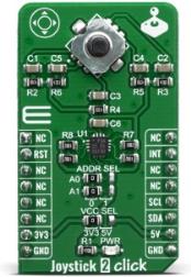
The click board™ also features an onboard jumper selector, which is used to select the voltage level that is connected to the microswitch input pin, making it usable for both 3V3 and 5V capable microcontoller pins.
Specifications
| Type |
Pushbutton/Switches |
| Applications |
Cell phones, tablets, terminals, video games, toys, and many more. |
| On-board modules |
SKRHABE010 4-direction joystick switch with Center-push Function by Alps and Port Expander IC from NXP, PCA9538A
|
| Key Features |
High-quality microswitch, high mechanical and electrical durability, debouncing features |
| Interface |
GPIO,I2C |
| Click board size |
M (42.9 x 25.4 mm) |
| Input Voltage |
3.3V or 5V |
Pinout diagram
This table shows how the pinout on Joystick 2 click corresponds to the pinout on the mikroBUS™ socket (the latter shown in the two middle columns).
| Notes |
Pin |
 |
Pin |
Notes |
|---|
| |
NC |
1 |
AN |
PWM |
16 |
NC |
|
| Reset IN |
RST |
2 |
RST |
INT |
15 |
INT |
Interrupt Out |
| |
NC |
3 |
CS |
RX |
14 |
NC |
|
| |
NC |
4 |
SCK |
TX |
13 |
NC |
|
| |
NC |
5 |
MISO |
SCL |
12 |
SCL |
I2C Clock |
| |
NC |
6 |
MOSI |
SDA |
11 |
SDA |
I2C Data |
| Power Supply |
3.3V |
7 |
3.3V |
5V |
10 |
5V |
Power supply |
| Ground |
GND |
8 |
GND |
GND |
9 |
GND |
Ground |
Onboard settings and indicators
| Label |
Name |
Default |
Description |
|---|
| JP1 |
VCC SEL |
Left |
Power supply voltage selection. Left position 3V3, right position 5V |
| LD1 |
Power LED |
- |
Power LED indicates that the click is powered on |
| JS1 |
SWITCH |
- |
Onboard switch |
Joystick 2 click electrical specifications
| Description |
Min |
Typ |
Max |
Unit |
|---|
| Contact resistance |
- |
- |
100 |
m? |
| Mechanical durability (30 operations/min) |
- |
- |
1 milion |
cycles |
Software Support
We provide a library for the Joystick 2 click on our LibStock page, as well as a demo application (example), developed using MikroElektronika compilers. The demo can run on all the main MikroElektronika development boards.
Library Description
The library initializes and defines the I2C bus driver and drivers that offer a choice for writing data in register and reads data from register. The library includes function for Joystick position. The user also has the function for configuration joystick, reset module and function for read interrupt state.
Key functions:
uint8_t joystick2_getJoystickPosition() - Functions for get Joystick positionvoid joystick2_configuration(uint8_t cfgData) - Functions for configuration joystickvoid joystick2_reset() - Functions for reset module
Examples description
The application is composed of three sections :
- System Initialization - Initializes the I2C module and all the necessary GPIO pins
- Application Initialization - Initializes the driver init, resets the module, and enables all joystick positions
- Application Task - It reads the position of the joystick, if it detects that the joystick has moved from the zero position, it prints a message about the current position
void applicationTask()
{
    uint8_t joystickPos;
    char demoText[ 50 ];

    joystickPos = joystick2_getJoystickPosition();

    switch(joystickPos)
    {
        case _JOYSTICK2_BUTTON_ACTIVE:
        {
            mikrobus_logWrite("--- Button is pressed!!! ---", _LOG_LINE );
            Delay_ms( 300 );
            break;
        }
        case _JOYSTICK2_POSITION_RIGHT:
        {
            mikrobus_logWrite("--- Joystick position [RIGHT] ---", _LOG_LINE );
            Delay_ms( 300 );
            break;
        }
        case _JOYSTICK2_POSITION_LEFT:
        {
            mikrobus_logWrite("--- Joystick position [LEFT] ---", _LOG_LINE );
            Delay_ms( 300 );
            break;
        }
        case _JOYSTICK2_POSITION_UP:
        {
            mikrobus_logWrite("--- Joystick position [UP] ---", _LOG_LINE );
            Delay_ms( 300 );
            break;
        }
        case _JOYSTICK2_POSITION_DOWN:
        {
            mikrobus_logWrite("--- Joystick position [DOWN] ---", _LOG_LINE );
            Delay_ms( 300 );
            break;
        }
    }
}
The full application code, and ready to use projects can be found on our LibStock page.
Other mikroE Libraries used in the example:
Additional notes and informations
Depending on the development board you are using, you may need USB UART click, USB UART 2 click or RS232 click to connect to your PC, for development systems with no UART to USB interface available on the board. The terminal available in all MikroElektronika compilers, or any other terminal application of your choice, can be used to read the message.
mikroSDK
This Click board™ is supported with mikroSDK - MikroElektronika Software Development Kit. To ensure proper operation of mikroSDK compliant Click board™ demo applications, mikroSDK should be downloaded from the LibStock and installed for the compiler you are using.
For more information about mikroSDK, visit the official page.
Resources
Downloads