As a Lithium Iron Phosphate battery requires a very accurate current and voltage for charging, Charger 11 click can be a perfect solution for such a task. Charger 11 click is equipped with a highly integrated LiFePO4 battery charger. This click has a charging current control IC over SPI interface which ensures perfect and efficient charging. With Analog-To-Digital Converter through its 12-bit resolution and I2C interface, Charger 11 click has precise battery voltage monitoring. Charger 11 click meets all requirements for charging this higher specific capacity, but low-density batteries.
How Does It Work?
Charger 11 click is based on the MCP73123 - a highly integrated Lithium Iron Phosphate (LiFePO4) battery charge management controller for use in space-limited and cost-sensitive applications, from Microchip. MCP73123 is an efficient Lithium Iron Phosphate battery charger, thanks to specific charge algorithms for LiFePO4 batteries to achieve optimal capacity and safety in shortest charging time possible. Along with its small physical size, the low number of external components makes this IC ideally suitable for various applications. MCP73123 is designed to employ a constant current and constant voltage charge algorithm. The 3.6V factory preset reference voltage simplifies design. The fast charge constant current is set by a digital potentiometer, on this Click it is MCP4161 with external 1K resistor in series. The MCP73123 also limits the charge current based on the temperature during high power or high ambient conditions. This thermal regulation optimizes the charge cycle time while maintaining device reliability. PROG pin of the MCP73123 also serves as the enable pin, where on this Click it is wired in rheostat configuration with the digital potentiometer. That way the charging current can be controlled.
.jpg)
The digital potentiometer on Charger 11 click is MCP4161 which offers a wide range of product offerings using a SPI interface. WiperLock technology allows application-specific calibration settings to be secured in EEPROM. This digital pot is tied with charger IC over its P0A control pin. By assigning values on MCP4161 from 0 to 10 kiloohms battery charging can be controlled. As there is a 1 K resistor in series it can never be 0 ohms on MCP73123 chargers PROG pin. However, maximum resistance cannot exceed 11 kiloohms. Fast charging can be regulated with 10K on PROG pin to get 130 mA. To get 1000 mA digital potentiometer needs to go down to 0,1 K, along with external resistor, which makes 1,1 K. Communication with digital potentiometer on this Click and that way controlling the charger is done through SPI interface.
Another feature of Charger 11 click is a battery voltage monitoring which is done by using a MCP3221A5T Analog-To-Digital converter. It is a 12-bit resolution SOT12 package device which provides one single ended input and is based on advanced CMOS technology. Communication to the MCP3221A5T is done by I2C interface where standard and fast modes are available for this device.
Charger 11 click for voltage reference use a MCP1541, which has a high precision output voltage of 4.096 volts, and which is then compared to battery voltage in order to get precise measurements. This voltage reference circuit uses a combination of an advanced CMOS design and EPROM timing to provide initial tolerance of ±1% max.
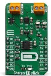
On the right side of the click board is an input screw terminal with corresponding markings, where the recommended external voltage of 6V can be applied. The left screw terminal is reserved for a Lithium Iron Phosphate battery with GND and VBAT+ markings. When connected to power source, the green PWR LED will indicate it. Red LED1 and green LED2 can be used for visual charge monitoring. As those two LEDs are multipurpose, they can be used for various things.
Specifications
| Type |
Battery charger |
| Applications |
Charger 11 is a perfect choice for development LiFePO4 battery charging applications. It offers two screw terminal connections, LED indicators for fast and easy prototyping. |
| On-board modules |
MCP73123, a highly integrated Lithium Iron Phosphate LiFePO4 battery charge management controller. |
| Key Features |
Designed for safe and efficient charging one LiFePO4 battery, battery voltage monitoring, two screw terminals, two multipurpose indicators over LEDs and mikroBUS™ pins, etc. |
| Interface |
I2C,SPI,GPIO |
| Click board size |
M (42.9 x 25.4 mm) |
| Input Voltage |
3.3V,5V |
Pinout diagram
This table shows how the pinout on Charger 11 click corresponds to the pinout of the mikroBUS™ socket (the latter shown in the two middle columns).
| Notes |
Pin |
 |
Pin |
Notes |
|---|
| Red LED Indicator |
LR |
1 |
AN |
PWM |
16 |
LG |
Green LED Indicator |
| |
NC |
2 |
RST |
INT |
15 |
ST |
Status Out |
| Chip Select |
CS |
3 |
CS |
RX |
14 |
NC |
|
| Serial Clock |
SCK |
4 |
SCK |
TX |
13 |
NC |
|
| Serial data out |
SDO |
5 |
MISO |
SCL |
12 |
SCL |
I2C Clock |
| Serial data in |
SDI |
6 |
MOSI |
SDA |
11 |
SDA |
I2C Data |
| Power Supply |
3.3V |
7 |
3.3V |
5V |
10 |
5V |
Power Supply |
| Ground |
GND |
8 |
GND |
GND |
9 |
GND |
Ground |
Software Support
We provide a library for the Charger 11 click on our LibStock page, as well as a demo application (example), developed using MikroElektronika compilers. The demo can run on all the main MikroElektronika development boards.
Library Description
Library contains function for getting INT pin state Library contains functions for setting AN, PWM and CS pin states Library contains function for spi transfer Library contains functions for getting and setting registers via SPI Library contains functions for wiper increment and decrement Library contains function for getting wiper position Library contains function for getting raw adc data Library contains function for getting output voltage
Key functions:
void charger11_spi_increment_wiper( void ) - increments wiper position by sending 8bit increment wiper commandvoid charger11_spi_decrement_wiper( void ) - decrements wiper position by sending 8bit decrement wiper commandfloat charger11_i2c_get_volt( float reference_voltage ) - gets raw ADC data and converts it to voltage based on reference voltage setting
Examples description
The application is composed of three sections :
- System Initialization - Initalizes INT, PWM, CS, AN pins and SPI, I2C, LOG modules
- Application Initialization - Initializes SPI and I2C drivers
- Application Task - Waits for user input in order to increment, decrement wiper or log report (Wiper position and Output voltage)
void applicationTask( )
{
    uart_ready = UART_Data_Ready( );

    if (uart_ready == 1)
    {
        uart_char = UART_Read( );

        switch (uart_char)
        {
            case '+' :
            {
                charger11_case_Plus( );
                break;
            }
            case '-' :
            {
                charger11_case_Minus( );
                break;
            }
            case 'r' :
            {
                charger11_case_Report( );
                break;
            }
            default :
            {
                mikrobus_logWrite( "> Invalid command", _LOG_LINE );
                break;
            }
        }
    }
}
Additional Functions :
- charger11_FloatCut( ) - Rounds float value to two decimals
- charger11_log_wiper_position( ) - Logs current Wiper position
- charger11_case_Plus( ) - Increments Wiper position
- charger11_case_Minus( ) - Decrements Wiper position
- charger11_case_Report( ) - Logs current Wiper position and Output voltage
The full application code, and ready to use projects can be found on our LibStock page.
Other mikroE Libraries used in the example:
Additional notes and informations
Depending on the development board you are using, you may need USB UART click, USB UART 2 click or RS232 click to connect to your PC, for development systems with no UART to USB interface available on the board. The terminal available in all MikroElektronika compilers, or any other terminal application of your choice, can be used to read the message.
mikroSDK
This Click board™ is supported with mikroSDK - MikroElektronika Software Development Kit. To ensure proper operation of mikroSDK compliant Click board™ demo applications, mikroSDK should be downloaded from the LibStock and installed for the compiler you are using.
For more information about mikroSDK, visit the official page.
Resources
Downloads