How does it work?
The Dual LIN click is a dual transceiver for the Local Interconnect Network (LIN) with integrated wake-up and protection features. The Dual LIN click is designed for in-vehicle networks using data transmission rates up to 20 kbps. This Click board™ contains the TLE7268SKXUMA1 from Infineon, Dual LIN click includes two independent transceivers that operate as bus drivers between the protocol controller and physical LIN networks.

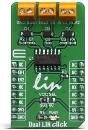
The Dual LIN click communicates with the MCU by using the UART RX and TX signals. RX and TX signals are also routed to the header on the edge of the click board™ so they can be used independently of the mikroBUS™ socket. Its most important features are the fact that it is a two separate single-wire LIN transceiver bus for transmission rates up to 20 kbps and it is compliant to ISO 17987-4 and LIN Specification 2.2A.
The EN1 and EN2 pins are used to enable the functionality of BUS 1 or BUS 2 of the device. When the EN1 pin is set to a HIGH logic level, the BUS 1 of the device is set to work in the normal mode, with the transmission paths from TXD to LIN and from LIN to RXD both active.
When the EN2 pin is set to a HIGH logic level, the BUS 2 of the device is set to work in the normal mode, with the transmission paths from TXD to LIN and from LIN to RXD both active. When the EN1 pin is set to a LOW state, the BUS 1 of the device is put into silent mode, depending on the TX pin state. The EN1 pin has a pull-down resistor, so it is pulled to Ground if it is left afloat. When the EN2 pin is set to a LOW state, the BUS 2 of the device is put into silent mode, depending on the TX pin state. The EN2 pin has a pull-down resistor, so it is pulled to Ground if it is left afloat.
The Dual LIN click supports different modes of operation of the two transceivers for minimizing ECU current consumption in low power modes, a common INH output can be used for controlling external circuitry, for example voltage regulators. Based on the Infineon BiCMOS technology. It provides excellent ESD robustness together with very high electromagnetic compliance (EMC). The TLE7268SKXUMA1 reaches a very low level of electromagnetic emission (EME) within a broad frequency range and independent from the battery voltage. The TLE7268SKXUMA1 is AEC qualified and tailored to withstand the harsh conditions of the automotive environment.
Some of the key features that are incorporated in the TLE7268SKXUMA1 are overtemperature protection, undervoltage detection. The Dual LIN click is digital I/O levels compatible with 3.3 V and 5 V microcontrollers, that it is optimized for high electromagnetic compliance (EMC) with very low electromagnetic emission and high immunity to interference. It also features two independent single-wire LIN transceivers in one device and gives out a transmission rate of up to 20 kbps.
Given the features included in this transceiver, the Dual LIN click can be used for Body Control Modules (BCM) and Gateway.
Specifications
| Type |
LIN |
| Applications |
Automotive applications: Body control modules (BCM) and Gateway |
| On-board modules |
TLE7268SKXUMA1, a Dual LIN transceiver from Infineon |
| Key Features |
Two independent single-wire LIN transceivers in one device, transmission rate up to 20 kbps, very low electromagnetic emission, High immunity to interference |
| Interface |
GPIO,UART |
| Compatibility |
mikroBUS |
| Click board size |
M (42.9 x 25.4 mm) |
| Input Voltage |
3.3V or 5V |
Pinout diagram
This table shows how the pinout on Dual LIN click corresponds to the pinout on the mikroBUS™ socket (the latter shown in the two middle columns).
| Notes |
Pin |
 |
Pin |
Notes |
|---|
| |
NC |
1 |
AN |
PWM |
16 |
NC |
|
| Output Enable |
EN1 |
2 |
RST |
INT |
15 |
NC |
|
| Output Enable |
EN2 |
3 |
CS |
RX |
14 |
TX |
UART Transmit |
| |
NC |
4 |
SCK |
TX |
13 |
RX |
UART Receive |
| |
NC |
5 |
MISO |
SCL |
12 |
NC |
|
| |
NC |
6 |
MOSI |
SDA |
11 |
NC |
|
| Power Supply |
3.3V |
7 |
3.3V |
5V |
10 |
5V |
Power Supply |
| Ground |
GND |
8 |
GND |
GND |
9 |
GND |
Ground |
Onboard settings and indicators
| Label |
Name |
Default |
Description |
|---|
| LD1 |
PWR |
- |
Power LED Indicator |
| TB1 |
BUS 1 |
- |
Terminal block for connecting LIN BUS 1 |
| TB2 |
BUS 2 |
- |
Terminal block for connecting LIN BUS 2 |
| TB2 |
VS |
- |
Terminal block for connecting LIN bus power supply voltage |
| TB2 |
VCC SEL |
Left |
Power supply voltage selection: left position 3.3V, right position 5V |
Dual LIN click electrical specifications
| Description |
Min |
Typ |
Max |
Unit |
|---|
| LIN bus supply voltage |
5 |
- |
40 |
V |
Software Support
We provide a library for the Dual LIN Click on our LibStock page, as well as a demo application (example), developed using MikroElektronika compilers. The demo can run on all the main MikroElektronika development boards.
Library Description
The library includes functions to write or read data from UART. You can set state of pins(RST - BUS1, CS - BUS2) you want to change it, and get state of pin(INT - INH).
Key functions:
void duallin_write_byte ( uint8_t input ) - Write single byte of datauint8_t duallin_read_byte ( void ) - Read single byte of datauint8_t duallin_byte_ready ( void ) - Check for new byte receiveduint8_t duallin_bus1_status ( uint8_t state ) - Sets state of bus1 pin
Examples description
The application is composed of three sections :
- System Initialization - Intializes UART module
- Application Initialization - Driver intialization
- Application Task - Choose one mode (read or write) of task. If you reading it checks if data is ready to be read and then reads one byte and if you are wiriting send data via UART.
void applicationTask(  )
{
    uint8_t tmp;
    char rec;
    uint8_t rdyFlag;
    uint8_t mode = DUALLIN_WRITE_MODE;

    if ( mode == DUALLIN_READ_MODE )
    {
        // RECEIVER - UART polling
        rdyFlag = duallin_byte_ready(  );

        if ( DUALLIN_DATA_READY == rdyFlag )
        {
            rec = duallin_read_byte(  );
            mikrobus_logWrite( &rec, _LOG_BYTE );
        }
    }
    else if ( mode == DUALLIN_WRITE_MODE )
    {
        // TRANSMITER - TX each 2 sec
        for ( tmp = 0; tmp < 11; tmp++ )
        {
            duallin_write_byte( MESSAGE_DATA[ tmp ] );
            if ( tmp < 6 )
            {
                Delay_ms( 100 );
            }
        }
        Delay_ms( 2000 );
    }
}
The full application code, and ready to use projects can be found on our LibStock page.
Other mikroE Libraries used in the example:
Additional notes and informations
Depending on the development board you are using, you may need USB UART click, USB UART 2 click or RS232 click to connect to your PC, for development systems with no UART to USB interface available on the board. The terminal available in all MikroElektronika compilers, or any other terminal application of your choice, can be used to read the message.
mikroSDK
This Click board™ is supported with mikroSDK - MikroElektronika Software Development Kit. To ensure proper operation of mikroSDK compliant Click board™ demo applications, mikroSDK should be downloaded from the LibStock and installed for the compiler you are using.
For more information about mikroSDK, visit the official page.
Resources
Downloads