How does it work?
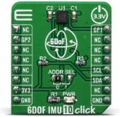
6DOF IMU 10 Click is a Click board™ which features the KMX62-1031 a 6 Degrees-of-Freedom inertial sensor from Kionix. It is based on the principle of a differential capacitance arising from accelerationinduced motion of the sense element, which utilizes common mode cancellation to decrease errors from process variation, temperature, and environmental stress. Capacitance changes are amplified and converted into digital signals which are processed by a dedicated digital signal processing unit.
The digital signal processor applies filtering, bias, and sensitivity adjustments, as well as temperature compensation. Magnetic sensing is based on the principle of magnetic impedance. The magnetic sensor detects very small magnetic fields by passing an electric pulse through a special electron spin aligned amorphous wire. Due to the high Curie temperature of the wire, the sensor's thermal performance shows excellent stability. Noise performance is excellent with bias stability over temperature. Bias errors resulting from assembly can be trimmed digitally by the user. These sensors can accept supply voltages between 1.7V and 3.6V, and digital communication voltages between 1.2V and 3.6V.
The Kionix KMX62 digital sensor can communicate on the I2C digital serial interface bus. This flexibility allows for easy system integration by eliminating analog-to-digital converter requirements and by providing direct communication with system processors. The I2C interface is compliant with high-speed mode, fast mode, and standard mode I2C protocols.
As previously mentioned, the KMX62 can communicate on an I2C bus. I2C is primarily used for synchronous serial communication between a Master device and one or more Slave devices. The system Master provides the serial clock signal and addresses Slave devices on the bus. The KMX62 always operates as a Slave device during standard Master-Slave I2C operation. I2C is a two-wire serial interface that contains a Serial Clock (SCL) line and a Serial Data (SDA) line. SCL is a serial clock that is provided by the Master, but can be held LOW by any Slave device, putting the Master into a wait condition. SDA is a bi-directional line used to transmit and receive data to and from the interface. Data is transmitted MSB (Most Significant Bit) first in 8-bit per byte format, and the number of bytes transmitted per transfer is unlimited. The I2C bus is considered free when both lines are HIGH.
Specifications
| Type |
Motion |
| Applications |
A accelerometer can be used to enable a variety of simultaneous features for Machine health, screen orientation, navigation. |
| On-board modules |
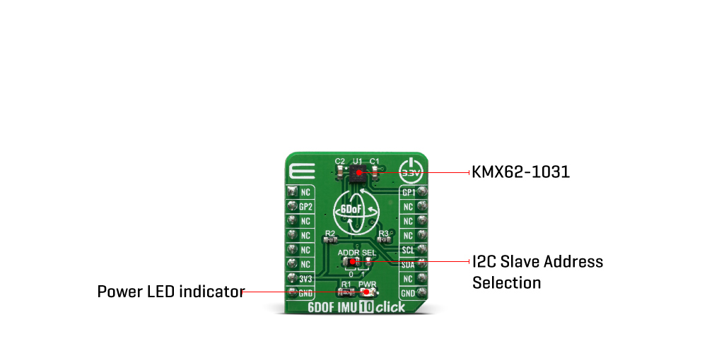
KMX62-1031, a 6 Degrees-of-Freedom inertial sensor from Kionix |
| Key Features |
16-bit digital output, Internal 384-byte FIFO buffer |
| Interface |
GPIO,I2C |
| Compatibility |
mikroBUS |
| Click board size |
S (28.6 x 25.4 mm) |
| Input Voltage |
3.3V |
Pinout diagram
This table shows how the pinout on 6DOF IMU 10 click corresponds to the pinout on the mikroBUS™ socket (the latter shown in the two middle columns).
| Notes |
Pin |
 |
Pin |
Notes |
|---|
| |
NC |
1 |
AN |
PWM |
16 |
GP1 |
General Purpose #1 |
| General Purpose #2 |
GP2 |
2 |
RST |
INT |
15 |
NC |
|
| |
NC |
3 |
CS |
RX |
14 |
NC |
|
| |
NC |
4 |
SCK |
TX |
13 |
NC |
|
| |
NC |
5 |
MISO |
SCL |
12 |
SCL |
I2C Clock |
| |
NC |
6 |
MOSI |
SDA |
11 |
SDA |
I2C Data |
| Power Supply |
3.3V |
7 |
3.3V |
5V |
10 |
NC |
|
| Ground |
GND |
8 |
GND |
GND |
9 |
GND |
Ground |
Onboard settings and indicators
| Label |
Name |
Default |
Description |
|---|
| LD1 |
PWR |
- |
Power LED Indicator |
| JP1 |
ADDR SEL |
Left |
Select I2C address bit: Left postion 0, Right position 1 |
Software Support
We provide a library for the 6DOF IMU 10 Click on our LibStock page, as well as a demo application (example), developed using MikroElektronika compilers. The demo can run on all the main MikroElektronika development boards.
Library Description
The library performs a magnetometer, accelerometer and temperature measurements and control of the 6DOF IMU 10 Click board. User also can select a desired range, scale and other config for the desired measurement. For more details check documentation.
Key functions:
void c6dofimu10_default_cfg ( void ) - Default module configuration functionvoid c6dofimu10_get_accel_axis ( c6dofimu10_axis_t *axis ) - Accelerometer axis datavoid c6dofimu10_get_mag_axis ( c6dofimu10_axis_t *axis ) - Magnetometer axis data
Examples description
The application is composed of three sections :
- System Initialization - Initializes I2C driver and GP1 - GP2 pins used as interrupt pins. And initializes the LOG module.
- Application Initialization - Runs a communication test that reads device id (registry Who_I_AM). It then starts the default module config that sets the module to its initial state of operation.
- Application Task - Reads the accelerometer and magnetometer axis data. And reads temperature values. All data logs on the USBUART.
void application_task ( )
{
    c6dofimu10_axis_t accel_axis;
    c6dofimu10_axis_t mag_axis;
    float temperature;

    c6dofimu10_get_accel_axis ( &accel_axis );
    c6dofimu10_get_mag_axis ( &mag_axis );
    temperature = c6dofimu10_get_temperature ( C6DOFIMU10_TEMP_FORMAT_CELSIUS );

    mikrobus_logWrite( "-- Accelerometer axis --", _LOG_LINE );
    app_display_axis_data( &accel_axis );
    Delay_ms( 2000 );

    mikrobus_logWrite( "-- Magnetometer axis --", _LOG_LINE );
    app_display_axis_data( &mag_axis );
    Delay_ms( 2000 );

    mikrobus_logWrite( "-- Temperature data --", _LOG_LINE );
    app_display_temp_data( temperature );
    Delay_ms( 2000 );
}
Additional Functions :
- app_display_axis_data ( ) - Display (accel and mag) axis data
- app_display_temp_data ( ) - Display temperature data
The full application code, and ready to use projects can be found on our LibStock page.
Other mikroE Libraries used in the example:
- I2C Library
- UART Library
- Conversions Library
Additional notes and informations
Depending on the development board you are using, you may need USB UART click, USB UART 2 click or RS232 click to connect to your PC, for development systems with no UART to USB interface available on the board. The terminal available in all MikroElektronika compilers, or any other terminal application of your choice, can be used to read the message.
mikroSDK
This Click board™ is supported with mikroSDK - MikroElektronika Software Development Kit. To ensure proper operation of mikroSDK compliant Click board™ demo applications, mikroSDK should be downloaded from the LibStock and installed for the compiler you are using.
For more information about mikroSDK, visit the official page.
Resources
Downloads