Search
Search for "click":
(Click here to search this entire website for "click" with Google.)
 |
|
|
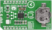
RTC6 click carries Microchip's MCP79410 Real-Time Clock/Calendar IC with built-in 64 bytes of battery-backed SRAM an additional 1 Kbit of EEPROM. 64 bits of protected EEPROM requires an unlock sequence to be unlocked, which makes it suitable for storing a unique ID or other critical information. RTC6 click tracks hours, minutes, seconds, days, months, years and weekdays, with leap year compensation until the year 2399. The clock frequency is derived from an onboard 32.768KHz crystal oscillator. Backup power is supplied by a coin-cell Lithium battery. RTC6 communicates with the target board MCU through the mikroBUS I2C interface (SCL, SDA) along with a multifunction pin (MFP, in place of default mikroBUS INT pin). The multifunctional pin (MFP) can be configured as an alarm, a square wave frequency output, or a general purpose output. The board is designed to use either a 3.3V or a 5V power supply. |
|
|
|
|
|
|
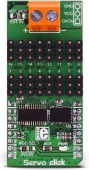
Servo click is a 16-channel PWM servo driver with the voltage sensing circuitry. It can be used to simultaneously control 16 servo motors, each with its own programmable PWM signal. The frequency of the control PWM signal can be programmed in the range from 24 Hz to 1526 Hz, which is an ideal range for driving various types of servos. An accurate 16bit A/D converter is used to sample the voltage drop across the shunt resistor on each of the 16 channels, giving feedback on the servo current consumption. This way, Servo click is able to provide an information about the servo operation parameters, with no additional modifications of the servo itself. |
|
|
|
|
|
|
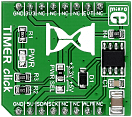
Timer click is a mikroBUS add-on board with Maxim's DS1682 total elapsed time recorder. The main feature of the IC is its elapsed time counter (ETC) used in conjunction with the ALARM pin. Whenever the EVENT pin is held high, the ETC will track time in quarter second resolution. Once the EVENT pin is set to logic low, the time data will be written in the IC's non volatile EEPROM. The next time the EVENT pin is pulled high, the timer will pick up where it left and continue measuring accumulated time. The upper limit is 34 years. In practical applications, the ALARM pin will be utilized to set off a flag once a certain threshold of accumulated time is reached. The alarm flag is one time programmable. The board communicates with the target MCU through the mikroBUS I2C interface, with two additional pins: ALARM (in place of default INT) and EVENT (in place of RST). Designed to use either a 3.3V or a 5V power supply. |
|
|
|
|
|
|
|
UNI Clicker is a compact development board designed with four mikroBUSâ„¢ sockets for Click Board connectivity. It is a complete solution for building your own gadgets with unique functionalities. |
|
|
|
|
|
|
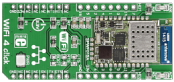
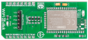
WiFi 4 click carries SPWF01SA, a complete standalone WiFi module with a single-chip 802.11 b/g/n transceiver, a 32-bit STM32 MCU, along with a built-in 2.4 GHz ISM band antenna. The onboard module has 1.5 MB of internal flash and 64 KB of RAM, plus a fully integrated TCP/IP protocol stack with added web server and application service capabilities. WiFi4 click communicates with the target MCU through the mikroBUS UART interface, but the board also features additional 14 GPIO pins. Uses a 3.3V power supply only. |
|
|
|
|
|
|
WiFi 6 click is a mikroBUS™ add-on board with Bluegiga's WF121-A self-contained Wi-Fi module. With a fully integrated radio and 32-bit microcontroller, this module is ideal for embedded applications.
The module's 2.4GHz band radio is fully compliant with IEEE 802.11b/g/n and offers excellent radio performance. Allows end user applications to be embedded onto the integrated PIC32MX695H, a 32-bit 80MHz microcontroller with 128KB RAM and 512KB Flash memory, for development of lower-cost and smaller sized products. Also integrated on-board is a single power supply.
WiFi 6 click communicates with the target MCU through the mikroBUS™ UART (TX, RX), SPI, or IC2, with additional functionality provided by CTS pin (in place of default mikroBUS™ INT pin); a mikroProg connector allows to update the firmware of the internal PIC32. SPI interface can be accessed by jumpers on the click board. The board is designed to use a 3.3 power supply only. |
|
|
|
|
|
|
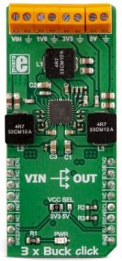
3xBuck click is a triple step-down (buck) converter Click board™. It features three independent output terminals that can provide 1.8V, 3.3V, and 5V with the combined current output up to 3A. This specific selection of output voltages makes this Click board™ a perfect choice for an embedded application power supply, as these voltages are the most commonly used values. The voltage at each output can be switched to a programmable internal voltage divider, in cases when the output voltage fine-tuning is required. This can be done over the industry-standard I2C interface. |
|
|
|
|
|
|
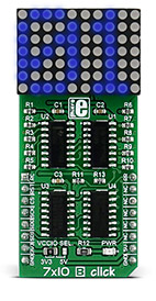
70 super bright blue LEDs for displaying the most versatile set of symbols and characters
7x10 B click displays letters, numbers, and characters in a 7x5 font resolution. It carries a matrix of 70 blue LEDs driven by a pair of 8-bit serial-in, parallel-out shift registers, a Darlington Transistor array and a Johnson counter.
The display has the capability to scroll the text across the screen. |
|
|
|
|
|
|
7x10 G click can be used for displaying letters on a display with 7x5 font resolution. It carries a matrix of 70 green LEDs driven by a pair of 8-bit serial-in, parallel-out shift registers, a Darlington Transistor array and a Johnson counter.
7x10 G click is designed to run on either 3.3V or 5V power supply. It communicates with the target microcontroller over SPI interface, with additional functionality provided by the following pins on the mikroBUS™ line: AN, PWM, RST. |
|
|
|
|
|
|
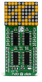
70 super bright yellow LEDs for displaying the most versatile set of symbols and characters
7x10 Y click displays letters, numbers, and characters in a 7x5 font resolution. It carries a matrix of 70 yellow LEDs driven by a pair of 8-bit serial-in, parallel-out shift registers, a Darlington Transistor array and a Johnson counter.
The display has the capability to scroll the text across the screen. |
|
|
|
|
|
<< First
< Previous
Next >
|
|


