Search
Search for "click":
(Click here to search this entire website for "click" with Google.)
 |
|
|
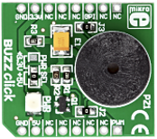
The Buzz Click board is an accessory board in mikroBus form factor. The board features a piezo speaker capable of emitting audio signals, with a resonant frequency of 3.8kHz. The on-board buzzer driver is connected to both the CS and PWM mikroBus lines. It is set to use the 5V mikroBus power supply by default, however soldering the PWR SEL SMD jumper to the 3.3V position will allow it to be used with 3.3V mikroBus systems. |
|
|
|
|
|
|
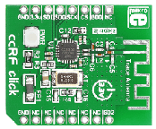
ccRF click is a low-power 2.4 GHz transceiver designed for the 2400- 2483.5 MHz ISM and SRD frequency bands. It features the CC2500 Low-Power 2.4 GHz RF transceiver as well as PCB trace antenna. The CC2500 is integrated with a highly configurable baseband modem that supports various modulation formats and has data rate up to 500 kBaud. Maximum device range is up to 20 meters in open space. ccRF click communicates with the target microcontroller via mikroBUS SPI, RST and PWM lines. The board is designed to use 3.3V power supply only. All these features make this board ideal for consumer electronics, wireless audio, wireless keyboard and mouse RF remote controls. |
|
|
|
|
|
|
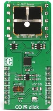
CO 2 click is a very accurate, carbon-monoxide-gas-sensor Click board™, equipped with the SPEC amperometric, 3SP CO 1000 gas sensor which electrochemically reacts with the carbon monoxide (CO). It is supported by the LMP91000, a high-precision integrated analog front-end IC (AFE), perfectly suited for use in electrochemical, sensing applications. The Click board™ also provides the reference voltage required by the sensor and it offers a choice between the analog output from the AFE IC buffered with the low noise op-amp, and the digital output from the 12-bit SAR A/D converter. |
|
|
|
|
|
|
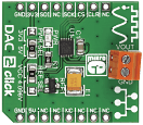
DAC2 click carries LTC2601CDD, a 16-bit digital-to-analog converter, along with voltage output screw terminals. The chip has high rail-to-rail output drives (±15mA, Min) and double-buffered data latches. The click board communicates with the target MCU through the mikroBUS SPI interface with clock rates up to 50MHz. Additionally, the CLR pin, in place of default mikroBUS RST pin, clears all the registers. The board uses either a 3.3V or 5V power supply. You can also set the reference voltage either to VCC or 4.096V. |
|
|
|
|
|
|
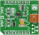
DAC3 click carries Microchip's MCP4726 IC, a 12-bit digital-to-analog converter, along with voltage output screw terminals. The digital value is converted to the appropriate voltage level in the range between GND and REFERENCE (VCC or 4.096V), which is proportional to the received 12-bit number. MCP4726 also integrates EEPROM for storing DAC register and configuration bit values. The board communicates with the target board MCU through the mikroBUS I2C interface (SCL, SDA pins). Standard (100 kHz), fast (400 kHz) and highspeed (3.4 MHz) I2C modes are available. Uses either a 3.3V or a 5V power supply. |
|
|
|
|
|
|
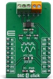
DAC 4 Click carries Microchip's MCP4728 IC, a Quad Digital-to-Analog Converter with nonvolatile (EEPROM) Memory. The digital value is converted to the appropriate voltage level in the range between GND and VCC, which is proportional to the received 12-bit number. MCP4726 also integrates EEPROM for storing DAC register and configuration bit values. These options give a lot of flexibility which make it a perfect choice for an accurate and simple generation of analog signals for various purposes, such as PLC/DCS modules, temperature and pressure control, medical and scientific instrumentation, chromatography and other similar applications, where accurate digital to analog conversion is needed.
DAC 4 click board™ is supported by a mikroSDK compliant library, which includes functions that simplify software development. This Click board™ comes as a fully tested product, ready to be used on a system equipped with the mikroBUS™ socket.
|
|
|
|
|
|
|
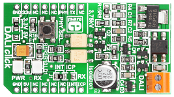
DALI Click is a compact board that enables you to add Digital Addressable Lighting Interface (DALI) to your design. The board features two optocouplers, a push button and screw terminals. DALI Click communicates with the target board via four mikroBUS lines (RST, CS, PWM and INT). Data between MCU and devices is transferred over two-wire differential bus by means of an asynchronous, half-duplex, serial protocol. It is possible to address up to 64 devices in a DALI stand alone systems and more than 64 devices as DALI subsystems (gateways). The board is designed to use a 3.3V or 5V power supply, and has an LED diode to indicate the presence of power. |
|
|
|
|
|
|
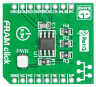
FRAM click brings 256Kbit (32,768 words x 8 bits) of Ferroelectric Random Access Memory to your design. It features the MB85RS256A module which uses the ferroelectric process and silicon gate CMOS technologies for forming the nonvolatile memory cells. It is able to retain data without using a back-up battery. The memory can be used for 10 bilion read/write operations and does not take long time to write data unlike Flash memories or EEPROM. It uses SPI to communicate with the target device. Maximum operating frequency is 25MHz. The board is designed to use 3.3V power supply only. |
|
|
|
|
|
|
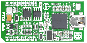
FTDI Click features the FT2232H dual high speed USB 2.0 to UART/I2C/SPI serial interface converter. It includes a DA converter and EEPROM as well. The entire USB protocol is handled on the chip (FTDI USB drivers are required), making this board ideal for various USB applications. FTDI Click communicates with the target board via mikroBUS SPI (MOSI, MISO, SCK, CS), I2C (SDA, SCL), UART (Tx, Rx), RST, PWM, AN and INT lines. The board can be powered via USB or via mikroBUS socket. A green LED indicates the presence of power supply. |
|
|
|
|
|
|
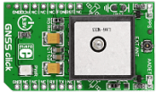
GNSS click carries Quectel’s L86 GNSS module with a patch antenna along with an external antenna connector. GNSS stands for Global Navigation Satellite System, an umbrella term that describes both the United States GPS and the Russian GLONASS global positioning systems. Excluding its wider applicability, the L86 module is similar to the L80 module (used on GPS3 click). It includes the same set of technologies: automatic prediction of orbits from internally stored data, adaptive adjusting of on/off time to balance between positioning accuracy and power consumption etc. The board uses a 3.3V power supply. |
|
|
|
|
|
<< First
< Previous
Next >
|
|


