Search
Search for "click":
(Click here to search this entire website for "click" with Google.)
 |
|
|
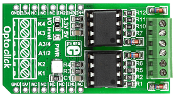
OPTO Click is an accessory board in the mikroBUS form factor. It features two VO2630 dual channel, high speed optocoupler modules. They enable high speed (10 MBit/s) data transfer between it's input and output with galvanic isolation. The optocouplers are connected to four lines (INT, CS, RST and AN) on the mikroBUS socket. The board features six screw terminals for easier connections and an LED indication of power supply. The board requires a 5V power supply, however an SMD jumper is available for selecting between 3.3V or 5V communication levels. |
|
|
|
|
|
|
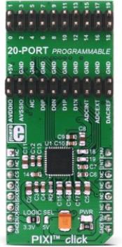
PIXI™ click is equipped with MAX11300 IC from Maxim Integrated, which features Maxim Integrated's versatile, proprietary PIXI™ technology - it is the industry's first configurable 20-channel mixed-signal data converter. Besides the 12bit multichannel SAR ADC and buffered DAC, it also features one internal and two external temperature sensors for tracking the junction and the environmental temperatures. Adjacent pairs of ports can be configured as logic-level translators for open-drain devices or analog switches. Each port is individually configurable with up to four selectable voltage ranges within -10 V to +10 V.
PIXI™ ports provide highly flexible hardware configuration for 12-bit mixed-signal applications. The MAX11300 is best suited for applications that demand a mixture of several analog and digital functions, such as monitoring and adjusting the bias on the power amplifiers, digital level shifters, automatic fan speed controllers, etc. Actually, it can easily adapt to specific application requirements, allowing for an easy reconfiguration, which makes it usable in virtually any embedded application. |
|
|
|
|
|
|
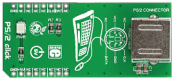
PS/2 click is a cost-effective solution for adding keyboard and mouse connectivity to your design. It features a standard 6-pin Mini-DIN PS/2 connector, a mikroBUS host socket, and a power indicator LED. PS/2 click communicates with the target board through mikroBUS RST (data) and CS (clock) pins, and the board is designed to use a 5V power supply only.
Tip: PS/2 keyboards support full N-key rollover, which is the ability of the keyboard to handle any number of simultaneous keystrokes! |
|
|
|
|
|
|
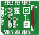
REED click is a simple board that carries a standard (Single Pole Single Throw Normally Open) reed switch. A reed switch comprises of two thin magnetic contacts sealed inside a casing. One contact is a magnetic north pole, the other a south. The two contacts are separate, until a magnetic field is applied which snaps them close, activating the switch. A single mikroBUS pin (CS) connected to the MCU outputting a 1 or 0 depending on the whether the switch is close or open. REED click is designed to use either a 3.3V or a 5V power supply. |
|
|
|
|
|
|
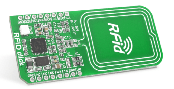
RFid click is an accessory board in mikroBUS form factor. It is a compact and easy solution for adding RFid to your design. It features a CR95HF 13.56 MHz contactless transceiver as well as a trace antenna. RFid click communicates with the target board microcontroller via mikroBUS UART (TX, RX), SPI (MISO, MOSI, SCK, CS) INT, RST, PWM and AN lines. The board is designed to use a 3.3V power supply only. An LED diode (GREEN) indicates the presence of power supply. CR95HF IC is a RFid module with an integrated transceiver for contactless applications. The board contains a dedicated internal frame controller and analog front end (AFE) for RF communications. |
|
|
|
|
|
|
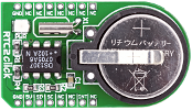
The RTC2 Click board is an accessory board in mikroBus form factor, featuring the DS1307 serial real-time clock (RTC). It is a low-power, full binary-coded decimal (BCD) clock/calendar with programmable square-wave output signal. The board uses the I2C interface for communication, and can only be used with a 5V power supply. The board features a 3V/230mA lithium battery as a backup power supply, which ensures that timekeeping operation continues even when the main power supply turns off. |
|
|
|
|
|
|
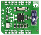
RTC3 click carries BQ32000, a real time clock with an integrated trickle charge circuit for automatic switchover to a backup power supply (the circuit maintains the backup charge with an onboard super capacitor). The clock frequency is derived from an onboard 32.768KHz oscillator. RTC3 click communicates with the target board microcontroller through mikroBUS I2C lines: SCL, SDA. In addition, the INT pin serves as a configurable interrupt output. The board is designed to use a 3.3V power supply only. |
|
|
|
|
|
|
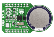
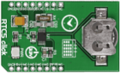
RTC4 click carries DS2417, a real time clock/calendar with a 1-Wire MicroLAN interface and a programmable interrupt for system output. The clock frequency is derived from an onboard 32.768KHz oscillator. An integrated backup energy source maintains a charge with an onboard coin cell supercapacitor. The clock has an accuracy of +/-2 minutes per month at a 25 degrees Celsius temperature. Depending on the position of the onboard jumper, RTC4 click communicates with the target board MCU either through mikroBUS AN or PWM pin (here, GPI01, GPIO0), plus the INT pin. The board is designed to use either a 3.3V or 5V power supply. |
|
|
|
|
|
|
RTC5 click carries MCP79510, a real-time clock/calendar with an SPI interface (mikroBUS MISO, MOSI, SCK and CS pins); along with a programmable interrupt for system output. The clock frequency is derived from an onboard 32.768KHz oscillator. For backup power, RTC5 click has a coin-cell Lithium polymer battery connector. The chip has 64-bytes of battery-backed SRAM and 1 kbit of EEPROM for storing data, along with 128 bits of protected space for storing a unique ID. The clock/calendar automatically compensates for leap years and months shorter than 31 days. The board is designed to use a 3.3V power supply only. |
|
|
|
|
|
|
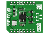
SRAM click lets you add 1Mbit of additional SRAM memory to your devices, via the 23LC1024 chip. It organizes the memory into 8-bit instruction registers and 32-byte pages. Three operating modes for reading and writing data are available: byte, page, and sequential (the last one allows read/write for the entire memory array). The clock rate for all three modes is up to 20MHz. The board communicates with the target MCU through the mikroBUS SPI interface (MISO, MOSI, SCK, CS) with additional HOLD functionality provided through the default mikroBUS RST pin. SRAM click is designed to use either a 3.3V or 5V power supply. |
|
|
|
|
|
<< First
< Previous
Next >
|
|


