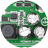
3.3V power supply
The Board is equipped with a power supply unit capable of supporting 3.3V microcontrollers and peripherals. It can be powered over a USB cable, or external adapter connectors.
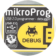
mikroProg™
Onboard mikroProg™ IN-Circuit Debugger and programmer supports all existing FT90x devices.
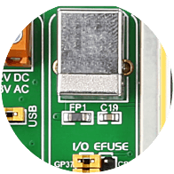
Programmer USB connector
Programmer USB port is connected to mikroProg™, but can also be used to power the board, or to permanently program the MCU using EFUSE.
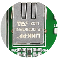
Ethernet Connector
Microcontrollers with internal ethernet support can be connected to this RJ-45 connector to establish ethernet communications.
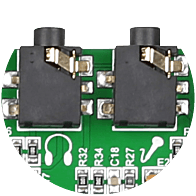
Audio connectors
Audio connectors enable you to connect headphones and a microphone with the audio codec chip and use it in your applications.
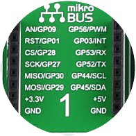
mikroBUS socket 1
EasyFT90x provides two mikroBUS™ sockets for MikroElektronika click™ boards. mikroBUS™ is a simple and effective Plug-and-Play connectivity solution.
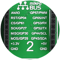
mikroBUS socket 2
EasyFT90x provides two mikroBUS™ sockets for MikroElektronika click™ boards. mikroBUS™ is a simple and effective Plug-and-Play connectivity solution.
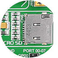
microSD card slot
microSD Card slot allows you to store large ammounts of data externally on microSD card using fast SPI communications.
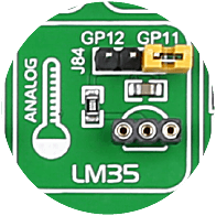
LM35 Temp Sensor
The LM35 is a low-cost precision integrated-circuit analog temperature sensor. It can measure temeperatures from -55C to +150C with 0.25C accuracy at room temperatures.
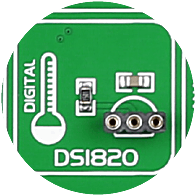
DS1820 Temp Sensor
Board supports Dallas DS1820 One-Wire digital temperature sensor. You can measure temperatures from -55C to +125C (-67F to +257F), with 0.5C accuracy.
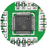
Stereo MP3 codec
VS1053 MPEG audio codec with SPI interface is available for audio input and output. Codec supports many compression file formats.
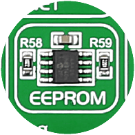
I2C EEPROM
You can store 8x256 bytes of configuration data or other data into on-board 24AA01 Serial EEPROM with I2C interface.
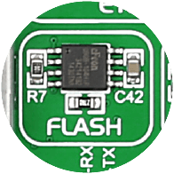
Serial Flash
Store up to 8 Mbit of data in M25P80 Serial Flash Memory with 25 MHz SPI Bus Interface. It suports over 100,000 aErase/Program Cycles per Sector and has over 20 Years of Data Retention.
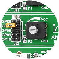
ADC potentiometers 1
You can simulate analog inputs using two provided analog potentiometers which can be connected to each of the 10 supported microcontroller analog input pins.
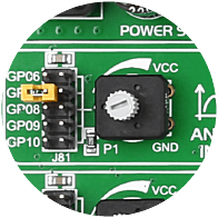
ADC potentiometers 2
You can simulate analog inputs using two provided analog potentiometers which can be connected to each of the 10 supported microcontroller analog input pins.
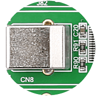
USB-UART connector
Fast on-board FTDI chip with USB connector, allows you to communicate with a PC or other UART devices using USB-UART connection.

TFT Display with Touch Panel
320x240 TFT Color Display with Touch Panel can display vivid and clear color images or advanced graphic content.
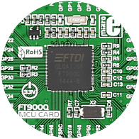
FT900 MCU
32-bit RISC FT32 core with 100MHz operation and True Zero Wait States (up to 3.1 DMIPS per MHz performance!) from 256KB of shadow memory. 64KB on-chip data memory, and 256kB of Flash.
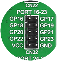
Right PORT Headers
We have provided additional PORT headers on the right side of the board, so you can access the desired microcontroller pins on the other side of the board too.
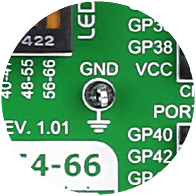
Oscilloscope GNDs
Three separate GND pins are available on the board for easier connection of GND reference for oscilloscope probes.
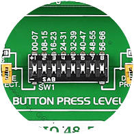
Button Press Level
Use these switches to pull-up or pull-down buttons in each input/output group.

Camera
OVA767 CMOS sensor can record 30fps at a VGA (640 x 480) resolution. It’s connected to the MCU through an 8-bit Parallel Camera Interface
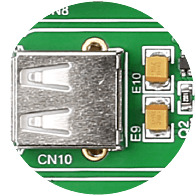
USB host connector 1
USB Device Connector is used for connecting the board with other devices such as a PC using fast USB 2.0 communication.
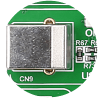
USB device connector 2
USB Host Connector enables your device to behave as a USB host. You can communicate with other USB slave devices, such as Flash Sticks, cameras, mp3 players and more.
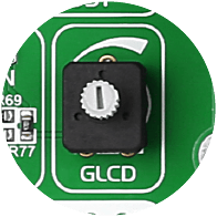
GLCD Contrast Potentiometer
This potentiometer allows you to adjust the contrast level of the pixels on your GLCD 128x64 display.
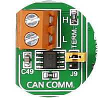
CAN support
Board contains MCP2551, a CAN controller chip connected to a screw terminal connector. This way you can implement industry-standard CAN communication with your device.
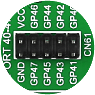
PORT Headers
Two male IDC10 port headers are available in each Input/Output group, which is convenient for easier access to any PORT pin.
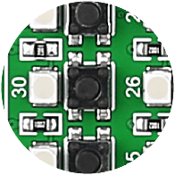
Push buttons
Push buttons in each Input/Output group enable you to have digital inputs on each port pin. Buttons are of high quality and have a stable response.
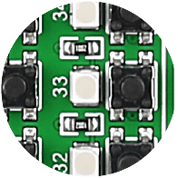
SMD LEDs
Each Input/Output PORT group contains SMD LEDs with low current consumption of only 1mA. The board contains 66 LEDs for PORT pins.
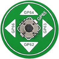
Navigation switch
Navigation switch can be used for handling the on-screen menus or as a generic input device.
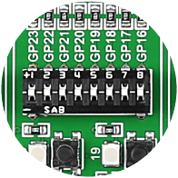
Tri-state DIP switches
Tri-state DIP switches are used to enable 4K7 pull-up or pull-down resistor on ony desired PORT pin.
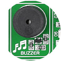
Piezo buzzer
With piezo buzzer you can debug your applications, or have audio signalization feature. It can be connected to two digital output pins, one of which is the output of PWM module.
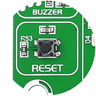
Reset button
High quality reset button with surrounding reset circuitry ensures stable reset operation.

Up-Close
Hover your mouse over different parts of the board in order to view the details up-close.

