RS485 click 3.3V is an RS422/485 transceiver Click board™, which can be used as an interface between the TTL level UART and the RS422/485 communication bus. It features a half-duplex communication capability, bus Idle, opens and short-circuit detection, glitch free power-up and power-down for hot-plugging applications, thermal shutdown, and more. It is well suited for transmitting data packets over long distances and noisy areas, using the twisted wire bus, which offers good electromagnetic interferences (EMI) immunity. ESD protection of the transceiver IC ensures reliable operation, exceeding 16kV for human body model (HBM).
Due to its robustness and reliability, the RS485 click 3.3V can be used in various applications that require reliable data transfer in various noisy environments, or over a substantial distance, when data rate transfer up to 1 Mbps is sufficient. RS485 3V3 click can be used for controlling various building automation systems, intelligent lighting systems (DMX), Point-of-Sale (POS) networks, and various other devices that need to establish a reliable communication over the RS422/485 bus.
How does it work?
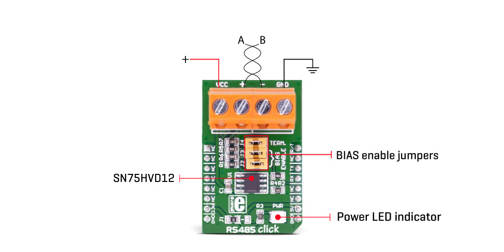
RS485 click 3.3V uses the SN75HVD12, an RS-422/485, half-duplex, tristate differential line driver and differential input line receiver, from Texas Instruments. This click is intended to be used as a physical layer device, often referred to as PHY, providing physical interfacing of the MCU TTL level UART lines with the RS422/485 bus. It is well suited for transmitting smaller blocks of data over long distances, using a twisted differential signal pair, for both TX and RX signals, allowing for half-duplex asynchronous communication. The SN75HVD12 transceiver consists of a separate driver and receiver sections, with Driver Enable and Receiver Enable pins (#RE and DE), used to enable the appropriate sections. Driver section is used to drive the RS422/485 bus with the signal received on the UART RX line labeled as D on the IC, while the receiver section returns data from the bus back to the MCU via the UART TX line, labeled as R on the IC in the schematics.
RS422/485 standard only specifies electrical characteristics of the transmitter and the receiver. It does not specify or recommend any communications protocol, only the physical layer. The top layer communication protocol of choice can be used, such as the MODBUS or similar protocols. Therefore RS485 3V3 click offers UART RX and TX pins, routed to the appropriate mikroBUS™ TX and RX UART pins. These pins are used by the MCU to send data to the RS485 bus, in a form determined by the user protocol. Additional DE and #RE pins are joined together and routed to the mikroBUS™ PWM pin. This pin is labeled as R/T on the Click board™. A pull-down resistor is used to determine states on these pins when they are left floating. Note that DE and RE pins use the opposite signal polarities for the active state, making it possible to drive them with a single MCU pin. When a HIGH logic level is applied to the R/T pin, transmitter becomes activated, while the receiver is deactivated at the same time - and vice versa. The R/T pin acts as a communication direction pin, in this configuration.
The SN65HVD31DR IC allows communication with data rates up to 1 Mbps. However, the maximal transfer speed is determined by the bus length: longer bus lines will result in less transfer speed. The RS422/RS485 bus needs to be terminated with the resistor on both ends (so-called parallel termination), which is equal to the characteristic impedance of the used cable, in order to prevent line reflections. The RS485 standard prescribes using a twisted pair cable as the data bus. Twisted pair cable tends to cancel common-mode noise and causes cancellation of the magnetic fields generated by the current flowing through each wire, thereby reducing the effective inductance of the pair.
The RS-485 standard specifies that a compliant driver must be able to drive 32 unit loads (UL), where 1 unit load represents a load impedance of approximately 12 kO. Since the SN65HVD31 device is 1/8 UL, up to 256 such receivers can be supported by a single driver.
The Click board™ is equipped with a jumper, that can be used to route the termination resistor of 120 O between the bus lines. The Click board™ is also equipped with two more jumpers, labeled as BIAS ENABLE. These jumpers are used to enable biasing of the bus by using pull-up and pull-down resistors between the bus differential lines and VCC/GND, respectively, preventing certain faulty conditions when no drivers are enabled on the bus, in addition to existing IC protection.
The SN75HVD12 receiver input hysteresis of about 35mV to enhance the noise immunity. The SN75HVD12 IC also features a true fail-safe receiver input, which guarantees a logic HIGH receiver output in cases when the receiver inputs are open or shorted, or when they are connected to a terminated transmission line with all drivers disabled.
There are two 2-pole screw terminals on board (VCC, +, -, GND) for connecting RS422/485 bus twisted pair cable, along with the GND and VCC. The terminal inputs labeled as “+†and “-†are used to connect the bus wires. GND and VCC rails can be used to provide the power supply for another node. Note that the VCC terminal is directly routed to the 3.3V rail of the mikroBUS™.
MikroElektronika provides a library that contains functions compatible with the MikroElektronika compilers, which can be used for working with the RS485 3V3 Click. The library also contains an example application, which demonstrates their use. This example application can be used as a reference for custom designs.
Specifications
| Type |
RS485 |
| Applications |
Interfacing the MCU UART module with the RS422/RS485 communication bus. Controlling various building automation systems, light controllers, sensors, and small embedded devices that can share the same bus |
| On-board modules |
SN75HVD12, an RS-422/485, half-duplex, tri-state differential line driver and differential input line receiver, from Texas Instruments |
| Key Features |
High communication speed up to 1Mbps, true failsafe protection, thermal shutdown, short circuit protection of the driver output, termination resistor selected with the jumper, bus biasing selected with jumpers |
| Interface |
UART |
| Compatibility |
mikroBUS |
| Click board size |
M (42.9 x 25.4 mm) |
| Input Voltage |
3.3V |
Pinout diagram
This table shows how the pinout on RS485 click 3.3V corresponds to the pinout on the mikroBUS™ socket (the latter shown in the two middle columns).
| Notes |
Pin |
 |
Pin |
Notes |
|---|
| |
NC |
1 |
AN |
PWM |
16 |
R/W |
Receive/Transmit |
| |
NC |
2 |
RST |
INT |
15 |
NC |
|
| |
NC |
3 |
CS |
RX |
14 |
TX |
UART transmit data |
| |
NC |
4 |
SCK |
TX |
13 |
RX |
UART receive data |
| |
NC |
5 |
MISO |
SCL |
12 |
NC |
|
| |
NC |
6 |
MOSI |
SDA |
11 |
NC |
|
| Power supply |
3.3V |
7 |
3.3V |
5V |
10 |
NC |
|
| Ground |
GND |
8 |
GND |
GND |
9 |
GND |
Ground |
RS485 click 3.3V electrical specifications
| Description |
Min |
Typ |
Max |
Unit |
|---|
| Bus common mode range |
-7 |
- |
12 |
V |
| Output Short-Circuit Current |
-250 |
- |
250 |
mA |
Onboard settings and indicators
| Label |
Name |
Default |
Description |
|---|
| LD1 |
PWR |
- |
Power LED indicator |
| JP2 |
BIAS ENABLE |
- |
Pull-up resistor enable the positive bus line (non-inverted line) |
| JP3 |
BIAS ENABLE |
- |
Pull-down resistor enable the negative bus line (inverted line) |
| JP4 |
TERM |
- |
Termination resistor enable |
Software support
We provide a demo application for the RS485 click 3.3V click on our LibStock page, as well as a demo application (example), developed using MikroElektronika compilers. The demo can run on all the main MikroElektronika development boards.
Library Description
Library initializes and defines GPIO driver and performs control of device voltage.
For more details check the documentation.
Key functions:
void rs485_writeByte(uint8_t input) - Write Single Byte.uint8_t rs485_readByte() - Read Single Byte.uint8_t ras485_byteReady() - Check for new byte received.
Example description
The application is composed of three sections:
- System Initialization - Initializes UART module.
- Application Initialization - Driver intialization.
- Application Task - (code snippet) - Checks if new data byte has been received in the RX buffer (ready for reading), and if it has then it reads one byte from the RX buffer. Otherwise, the application task writes the message data via UART.
void applicationTask()
{
 char tmp;
 uint8_t rdyFlag;

// RECEIVER - UART polling

 rdyFlag = rs485_byteReady();

 if (1 == rdyFlag)
 {
 tmp = rs485_readByte();
 mikrobus_logWrite( &tmp, _LOG_BYTE );
 }

// TRANSMITER - TX each 2 sec
/*
 for (tmp = 0; tmp < 9; tmp++)
 {
 rs485_writeByte( MESSAGE_DATA[tmp] );
 mikrobus_logWrite( "MESSAGE SENT", _LOG_LINE );
 }
 Delay_ms(2000);
*/

}
The full application code and ready to use projects can be found on our LibStock page.
Other mikroE Libraries used in this example:
Additional notes and information
Depending on the development board you are using, you may need USB UART click, USB UART 2 click or RS232 click to connect to your PC, for development systems with no UART to USB interface available on the board. The terminal available in all MikroElektronika compilers, or any other terminal application of your choice, can be used to read the message.
Resources
Downloads